HOME              PROFILE              SERVICES              PRODUCTS              DEAL WITH US              CONTACT US

SGC-AF2 AMF GENERATING SET CONTROLLER

INTRODUCTION

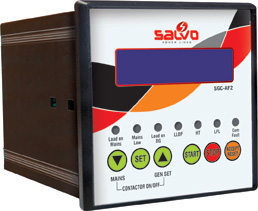
SGC-AF2 Automatic Mains Failure Module is a Microcontroller based digital control module, It has been very specially designed for the control of emergency and standby power system. It integrates the functions of Engine Start/Stop including the Protection for the generator set. An advanced single Chip Microcontroller has been used for and easy generator set control in the case of Mains Failures. SGC-AF2 initiates an Automatic generator set start cycle including load transfer to the generator by switching the generator contactors. After the main is restored the load will be automatically transferred back to mains by switching the mains contactor and the generator set will stop after a cooling time. The module has two basic operation modes: Auto and Manual modes can be chosen via the push-buttons mounted on the front panel. SGC-AF2 AMF Module has 24 parameters settings, which can be set by the operator in order to characterize the gen-set operation.

OPERATION

The SGC-AF2 has two basic operations.

  • AUTO MODE
  • MANUAL MODE

In Auto mode the Module controls the Generator set automatically according to the parameter settings.
In Manual mode the Module doesn’t react to the mains failure or mains restoration. All the operations have to be done manually.

PROGRAM MODE

User friendly sophisticated soft touch keys are provided on the front panel

  • To enter in the program mode press the “SET” key once and the default password will be displayed and if the password has not been changed you can enter the program mode by pressing the “SET” button
  • Once entered into the program mode all parameters can be selected using the “UP and DOWN” keys. Description of the parameters will be displayed on the LCD screen for an easy operation.
  • After selecting a parameter to enter into the editing of it press the “SET” button and use the “UP and DOWN” keys to change the settings after completing the setting press the “SET” key again to save the modified settings


AUTO MODE
MAINS FAILURE

In Auto mode of operation-In case the mains either fails or exceed operating limits then SGC-AF2 senses as mains failure and gives the command to start the Generator set. And on successful start of the Generator set (depends on the mains backup delay set) if all parameters are normal the load will automatically be transferred from the mains to the Generator set.

START SEQUENE

  • Start will be given to the Generator set. Message will be displayed on the LCD screen
  • If the Generator starts in the set number of attempts then the load will automatically transferred to the Generator set
  • If the Generator does not start in set number of attempts Then “FAIL TO START” message will be displayed in LCD screen
  • After generator starts if the cycle time is ‘ON’ stage, generator will stop only the completion of cycle off time. Again the mains fail detect generator will start only after a set time delay (cycle on time) and normal operation follow up

MAINS RESTORATION

When mains supply comes back to normal condition, SGC-AF2 then transfers the load from generator set to the Mains, after the restore time through Mains contactor. The generator cool down time will start and generator set will run with no load for specific time and then will stop automatically.
Mains Restore time is the time duration in which mains supply comes back in Specified voltage and the load is changed over from generator to mains. 

MANUAL MODE

 ٭START Sequence: Any Number of crank attempts can be done manually.
٭ STOP Sequence: Engine stop sequence is activated.

SALIENT FEATURES OF SGC-AF2

  1. Microcontroller based design
  2. Automatic start and stop
  3. Automatic load transfer
  4. Automatic engine protection
  5. Automatic shut down on faults namely
  • Over speed
  • Under speed
  • High temperature
  • Low lube oil pressure
  • Low fuel
  • DG volt abnormal
  • Over load
  • External stop
  • All fault and control indication
  • Alphanumeric LCD to show the display

INDICATIONS

  • Mains Low
  • Load on Mains
  • Load on DG
  • HT
  • LLOP
  • LFL
  • Common fault


SETTABLE PARAMETERS


Password setting

Factory set code is ____

To authorize entry into the setting menu. The password is necessary only  to change the settings

Mode selection

Auto Mode/
Manual Mode

We can select the mode either auto/manual using up/down keys

Mains fail delay

5s-99s

Set the required number of seconds for line failure duration timer

Mains backup delay (sec/min)

5s-55m

It is the time duration (seconds/minutes) between Mains failure & first crank to the generator

Mains backup delay(h)

Up to 10hrs

It is the time duration(hour) between Mains failure & first crank to the generator

Mains restore delay

5s-180s

It is the time duration in which mains supply comes back in specified range of voltage and the load is changed over from generator to mains

Mains low voltage

160v-190v

It is the minimum voltage  below, which mains fail  will occur

Mains high voltage

240v-270v

It is the maximum voltage above,
which mains fail will occur

Generator high voltage

240v-270v

It is the maximum voltage above, which generator fail will occur

Generator low voltage

160v-190v

It is the minimum voltage below, which generator fail will occur

Solenoid selection

ER-energized to Run
ES-energized to Stop

This setting (“ER" or "ES")
Determines the operating logic of the stop solenoid. We can select the solenoid type "ER" or "ES" using up/down keys.

Phase selection

Single phase
Three phase

The same unit can be used for three-phase as well as single -phase applications.

Cranking time

3s-20s

This is the time period for which generator starter is engaged or the crank to the generator remains hold.

Cranking interval

2s-180s

This is the time period between two successive cranks.

Generator on delay

30s-250s

This is the time interval after generator switching "ON" in which generator runs without load before 
Taking full load.

Generator cool down delay

20s-250s

This is the time interval in which generator runs without load before
switching off.

Generator build up delay

0s-99s

This is the rest period between
two consecutive start attempts

Stop solenoid delay

10s-60s

This is the stop solenoid activation time period.

Maximum frequency

50Hz-55Hz

If the generator frequency is more than the set value "over speed" message will display and generator will be shut off.

Minimum frequency

45Hz-50Hz

If the generator frequency is less than the set value "under speed"
message will display and generator will shut off.

Cycle time set

ON/OFF

We can set the cycle time either ON/OFF using up/down keys. The
Status is in "ON" stage we can set the Cycle off time & Cycle on time

Cycle off time

30m-8 hrs

This is the time period for engine stopping

ON timer

30m-5 hrs

This is the time period for retain
the back up delay

Cycle on time

30m-8 hrs

This is the time period for engine 
Starting.


KEY OPERATIONS

  • SET Key: Press the set key it will display the password, if the entered password is correct then we can enter into the parameters setting mode
  • ACCEPT/RESET Key: Operating this key clears the latched faults and reset the unit to start from fresh. While the first pressing reset the buzzer relay and the next time reset the common fail relay
  • UP/DOWN Key: The setting parameters are increased and decreased using these keys. When the controller is selected in the ‘Manual” mode the DOWN button is for the “Mains contactor ON and OFF” and the UP button for the “Generator
  • START/STOP BUTTON: In manual mode START and STOP button is to operate the engine manually

ALARMS
Fault alarms displayed in the LCD Monitor

    • SET FAILS TO START
    • LOW LUBE OIL PRESSURE
    • HIGH TEMPERATURE
    • LOW FUEL LEVEL
    • OVER SPEED
    • UNDER SPEED
    • OVER LOAD
    • DG VOLT ABNORMAL
    • LOW BATTERY
    • EXTERNAL STOP

“EXTERNAL STOPPING” will be displayed only if the generator set  has been forced to Stop By using the Emergency stop button which is fixed on the external side of the Enclosure"


PERFORMANCE SPECIFICATIONS


Sl. No:

Parameter

Specification

1

Aux supply

7.0-35.0 VDC

2

Aux supply Interruption time

1 second Sustains battery dip down to zero volts for one second without requiring external capacitor bank.

3

External capacitor bank

Not required

4

Generator voltage

160-300V AC (Ph-N)

5

Mains voltage

160-300V AC (Ph-N)

6

Rated frequency

50 / 60 Hz.

7

Voltage measuring tolerance

+ / -  1%

8

Frequency measuring  tolerance

+ / -  0.5%

FUSE SPECIFICATION


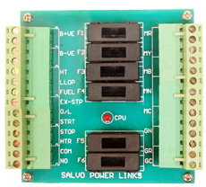
F1

Mains “R” Phase Fuse (Rating: 6A)

F4

Mains Contactor Fuse (Rating: 6A)

F2

Mains “Y” Phase Fuse (Rating: 2A)

F5

Generator “R” Phase Fuse (Rating: 6A)

F3

Mains “B” Phase Fuse (Rating: 2A)

F6

Generator Contactor Fuse (Rating: 6A)

TERMINAL CONNECTIONS


01

Battery positive

13

Common (Potential free contact)

03

Battery Negative

14

Normally Open contact

05

High Temperature

15

Mains “R” Phase

06

Low lube oil Pressure

17

Mains “Y” Phase

07

Low fuel level

19

Mains “B” Phase

08

External stop

21

Mains Neutral

09

Over load

23

Mains Contactor

10

Start

25

Generator Neutral

11

Stop

27

Generator “R” Phase

12

Hooter

28

Generator Contactor


SALVO POWER CONTROLS © 2013.Web designed by IDA Soft Tech